API 682 Mechanical Seal Plan 23: High-Temperature Boiler Feed Pump Reliability
Closed-loop pumping ring dynamics, energy dissipation comparisons against Plan 21, close-clearance throat bushings, and seal face vaporization prevention.
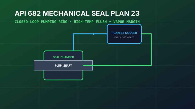
Table of Contents
In high-pressure boiler feed pump operation, the mechanical seal represents the component most vulnerable to catastrophic failure. Pumping saturated feedwater between 105°C (221°F) and 180°C (356°F) pushes mechanical seals to their absolute physical limits. The industry gold standard for addressing this challenge is API 682 Piping Plan 23.
1. The Hot Water Sealing Challenge (Fluid Vaporization)
A mechanical seal relies on a microscopic lubricating fluid film (typically 1 to 2 micrometers thick) maintained between the rotating and stationary seal faces. This liquid film must support hydraulic closing forces while dissipating frictional shear heat.
When pumping high-temperature boiler feedwater, the frictional heat generated at the seal interface easily elevates face temperature by 15°C to 25°C above bulk fluid temperature. If the bulk fluid is already near saturation, this localized temperature rise causes the lubricating film to flash violently into steam. The seal faces run dry, causing thermal stress cracking, blistered carbon faces, and immediate high-pressure leakage.
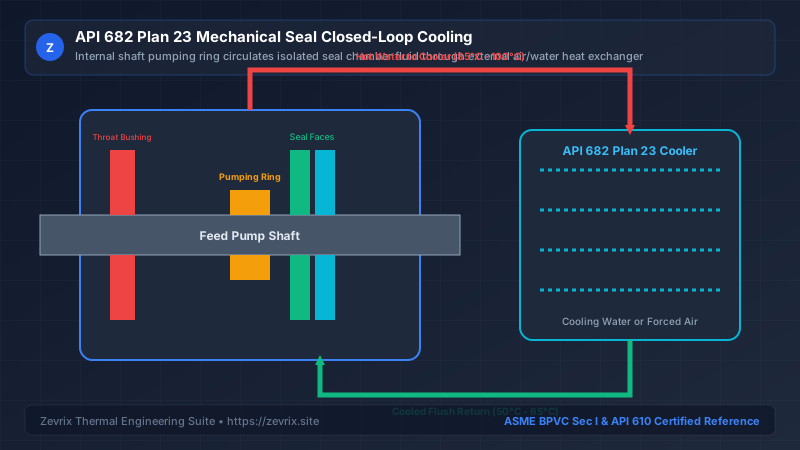
2. API 682 Plan 23 Closed-Loop Operating Architecture
3. Internal Pumping Ring Hydraulic Mechanics
Unlike Plan 21 or Plan 11 (which rely on pump discharge pressure to drive flush flow), Plan 23 relies entirely on an internal pumping device integrated into the rotating seal cartridge:
- Pumping Scroll (Helical Screw): A threaded sleeve rotating inside a close-clearance bore that functions as a miniature positive-displacement screw pump, ideal for high viscous drag.
- Bi-Directional Pumping Ring: A slotted cylindrical ring with tangential discharge ports that generates centrifugal pressure head (typically 0.4 to 1.2 bar differential) regardless of shaft rotation direction.
D_ring= Outer diameter of rotating pumping ring (m)ω= Rotational velocity in radians per second (rad/s)K_ring= Empirical hydraulic head coefficient (typically 0.35 to 0.55 depending on port radial clearance)
4. Parasitic Thermal Energy Loss: Plan 23 vs Plan 21
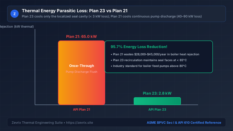
Plan 21 draws hot water from the pump discharge, cools it across a heat exchanger, flushes the seal, and dumps it into the pump suction. Plan 23 cools only the recirculating seal chamber volume:
| Design Metric | API Plan 21 (Once-Through Cooling) | API Plan 23 (Closed Recirculation Loop) |
|---|---|---|
| Flush Source | Continuous slipstream from pump discharge | Isolated seal chamber volume only (< 2 L) |
| Circulating Flow Rate | 8 to 15 L/min (2 to 4 gpm) | 4 to 8 L/min driven by internal pumping ring |
| Parasitic Heat Rejection | 40 kW to 90 kW thermal per seal | 1.5 kW to 3.0 kW thermal per seal |
| Annual Energy Cost (@ $0.08/kWh) | $28,000 to $60,000 / year / pump | $1,050 to $2,100 / year / pump |
| Cooling Water Consumption | High cooling water flow demand | Minimal cooling water; can use air-cooled fin-fan |
5. Close-Clearance Throat Bushing Isolation Design
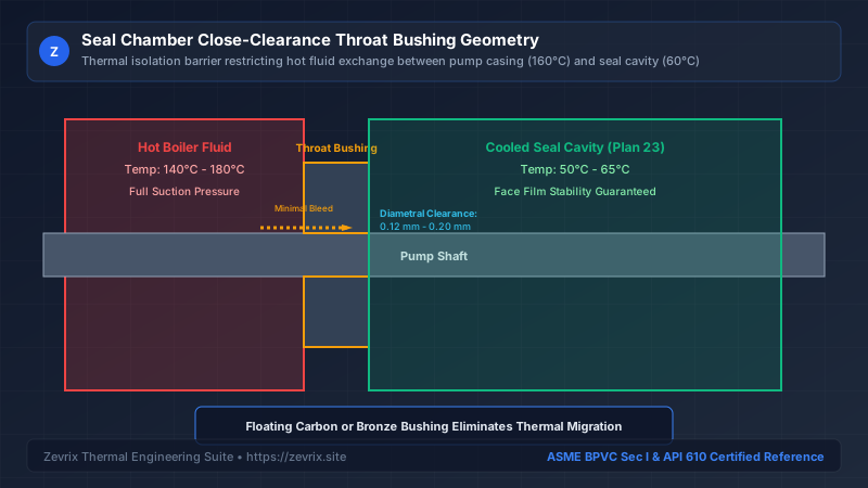
To prevent hot casing water from migrating into the seal chamber and overwhelming the Plan 23 cooler, API 682 mandates a close-clearance throat bushing:
- Fixed Bushing: Machined from bronze or 12% chrome steel with diametral clearance of 0.25 mm to 0.35 mm.
- Floating Carbon Bushing: Self-centering carbon-graphite segments held with a garter spring, achieving ultra-tight diametral clearance of 0.10 mm to 0.15 mm, reducing hot water infiltration by over 75%.
6. Seal Face Metallurgy & Silicon Carbide Grades
| Face Material Combination | Friction Coefficient μ | Thermal Conductivity | Suitability for Boiler Feed Service |
|---|---|---|---|
| Carbon vs Reaction-Bonded SiC (RB-SiC) | 0.08 - 0.12 | 120 W/m·K | Good for moderate temperatures (< 120°C); free silicon leaches in high pH |
| Carbon vs Sintered Silicon Carbide (SSiC) | 0.06 - 0.10 | 140 W/m·K | Zevrix Standard: Excellent chemical resistance in treated boiler water |
| Silicon Carbide vs Silicon Carbide (Hard/Hard) | 0.14 - 0.18 | 140 W/m·K | Vulnerable to dry running; only used if severe magnetite abrasives are present |
| Diamond-Coated SSiC vs SSiC | 0.02 - 0.04 | 600+ W/m·K | Ultra-low friction; withstands short dry-running transients during deaerator trips |
Try the Zevrix Interactive Boiler Feed Pump Calculator
Enter your boiler evaporation rate, operating drum pressure, and feedwater temperature to calculate exact mass flow, TDH, motor ratings, and cavitation margins with complete formula visibility.
Frequently Asked Questions
Marcus Vance, PE, M.Sc.
AuthorSenior Thermal Hydraulics & Fluid Machinery Specialist
Marcus Vance is a registered Professional Engineer with over 18 years of field and design experience in thermal power generation, industrial boiler feedwater systems, and API 610 rotating machinery.