Minimum Continuous Stable Flow (MCSF) & Automatic Recirculation Valve Sizing
Thermal runaway prevention, internal recirculation vibration, Automatic Recirculation Control (ARC) valve mechanics, and multi-hole restriction orifice design.
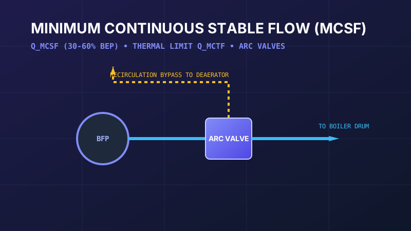
Table of Contents
In centrifugal pump engineering, operating at low flow is far more hazardous to machinery survival than operating at high flow. A boiler feed pump running against a closed discharge valve converts all electrical motor input energy into pure frictional heat within a confined liquid volume. Without a properly sized minimum flow recirculation bypass system, catastrophic pump destruction will occur within seconds.
1. Low-Flow Fluid Hazards: Thermal Runaway vs Recirculation
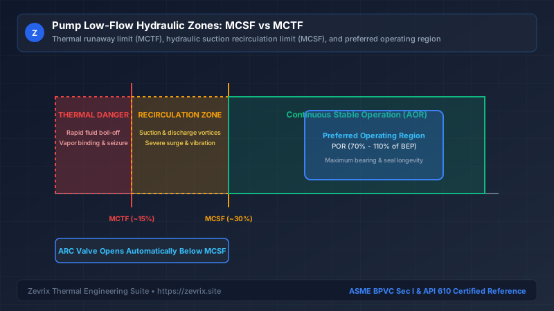
When a boiler feed pump throttles down below 30% of its Best Efficiency Point (BEP), two distinct destructive physical phenomena occur:
- Thermodynamic Thermal Runaway: Pump efficiency collapses toward zero at shutoff. Nearly 100% of driver shaft horsepower is absorbed by the trapped fluid as heat, driving liquid temperature above the saturation boiling point.
- Internal Hydraulic Recirculation: Fluid entering the impeller eye can no longer proceed smoothly into the discharge volute. Reverse flow vortices erupt at both the impeller suction tips and discharge tips, generating violent pressure pulsations, high-amplitude low-frequency vibration, and catastrophic seal face cocking.
2. MCTF vs MCSF Mathematical Derivation
Engineers must strictly differentiate between two distinct minimum flow limits:
P_shutoff= Shaft power consumed at zero flow / shutoff head (kW)ρ= Feedwater density (kg/m³)C_p= Specific heat capacity of feedwater (~4.2 kJ/kg·K)ΔT_allowable= Maximum allowable fluid temperature rise through the casing (typically 8°C to 12°C)
While Q_MCTF is typically 10% to 15% of BEP, operating continuously at this point will quickly destroy the pump through hydraulic recirculation. The Minimum Continuous Stable Flow (MCSF) is defined by the Hydraulic Institute and API 610 as the lowest flow rate at which the pump can operate continuously without exceeding allowable vibration limits:
3. API 610 Hydraulic Operating Zones (POR vs AOR)
| Hydraulic Zone | Flow Range (% of BEP) | Physical Behavior & Operational Guideline |
|---|---|---|
| Thermal Danger Zone | 0% to 15% BEP (< MCTF) | Forbidden. Fluid flashes into steam; casing clearance seizure within seconds. |
| Recirculation Zone | 15% to 30% BEP (MCTF to MCSF) | Permissible only during transient startup / shutdown for < 2 minutes. High vibration. |
| Allowable Operating Region (AOR) | 30% to 120% BEP | Stable continuous operation; vibration complies with ISO 10816 limits. |
| Preferred Operating Region (POR) | 70% to 110% BEP | Design sweet spot; optimal hydraulic efficiency, minimum radial thrust on bearings. |
4. Automatic Recirculation Control (ARC) Mechanics
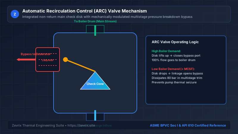
To safeguard feed pumps during rapid boiler load drops, facilities utilize self-contained Automatic Recirculation Control (ARC) valves mounted directly on the pump discharge nozzle:
| Minimum Flow Architecture | Operating Principle | Pros | Cons |
|---|---|---|---|
| Mechanical ARC Valve | Self-actuated non-return check disk mechanically linked to bypass trim | Failsafe; requires zero instrument air or electrical power; zero control lag | Higher initial valve cost; specialized maintenance overhaul |
| Active Control Valve Loop | Electromagnetic flowmeter + modulating globe valve + DCS logic | Modulates exact required flow; integrates into plant automation | Vulnerable to instrument air loss, power failure, or transmitter lag |
| Continuous Fixed Orifice | Permanently open restriction orifice bleeding continuously to deaerator | Simplest capital cost; zero moving parts | Massive continuous energy waste (wastes 25% of pump electrical power 24/7) |
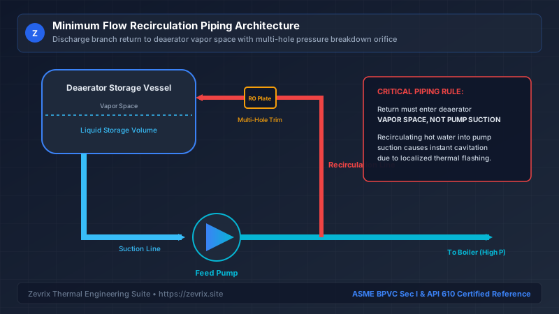
5. Bypass Piping Architecture & Deaerator Return Rules
6. Multi-Hole Breakdown Orifice Sizing
Dissipating 50 to 150 bar of pressure across the minimum flow bypass line requires specialized multi-hole or tortuous-path restriction orifice plates to avoid cavitation choking:
| Design Parameter | Single-Hole Sharp Orifice Plate | Multi-Hole Multi-Stage Orifice (Zevrix Recommended) |
|---|---|---|
| Pressure Drop Distribution | 100% of ΔP taken across 1 vena contracta | ΔP staged across 3 to 6 successive breakdown chambers |
| Cavitation Index σ | σ < 0.2 (Violent super-cavitation) | σ > 1.5 (Cavitation completely suppressed) |
| Acoustic Noise Generation | > 115 dBA (Severe structural pipe vibration) | < 82 dBA (Meets OSHA industrial workplace standards) |
| Erosive Service Life | Rapid wire-drawing failure within 3,000 hrs | Stellite-hardened trim exceeds 50,000 operating hours |
Try the Zevrix Interactive Boiler Feed Pump Calculator
Enter your boiler evaporation rate, operating drum pressure, and feedwater temperature to calculate exact mass flow, TDH, motor ratings, and cavitation margins with complete formula visibility.
Frequently Asked Questions
Marcus Vance, PE, M.Sc.
AuthorSenior Thermal Hydraulics & Fluid Machinery Specialist
Marcus Vance is a registered Professional Engineer with over 18 years of field and design experience in thermal power generation, industrial boiler feedwater systems, and API 610 rotating machinery.