Boiler Blowdown Rate Calculation & Two-Stage Heat Recovery Thermodynamics
TDS mass balance formulations, cycles of concentration, flash tank cyclonic steam recovery, and shell-and-tube economizer preheating.
Table of Contents
As water boils into steam inside an industrial steam drum, dissolved mineral salts, silica, and alkaline chemical compounds do not vaporize. They remain behind in the liquid water, concentrating continuously. Without regular purging through continuous blowdown, these solids deposit as insulating scale on heat transfer tubes, triggering severe overheating, tube rupture, and catastrophic priming that carries corrosive water into steam turbines.
1. Boiler Chemistry & The Necessity of Blowdown
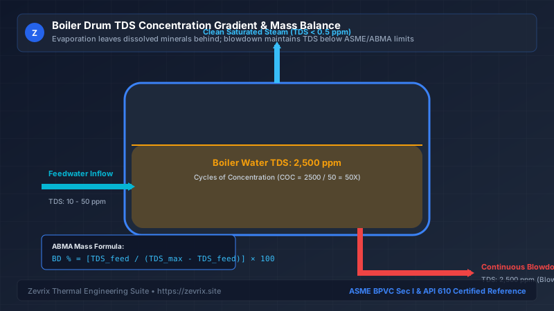
2. Mathematical TDS Mass Balance Derivation
At steady-state equilibrium, the mass of dissolved solids entering the boiler with feedwater must exactly equal the mass of solids leaving through continuous blowdown (assuming clean steam carries negligible solids):
Substituting Ṁ_feed = Ṁ_steam + Ṁ_blowdown into the mass conservation equation yields the standard continuous blowdown rate formula:
Blowdown %= Continuous blowdown mass flow rate expressed as a percentage of steam generation (%)TDS_feed= Total Dissolved Solids concentration in incoming feedwater (ppm or mg/L)TDS_drum,max= Maximum allowable TDS concentration in the boiler drum per ASME guidelines (ppm or mg/L)
3. Cycles of Concentration (COC) Optimization
The ratio of drum water concentration to feedwater concentration is termed Cycles of Concentration (COC):
| Feedwater Quality (Pretreatment) | Feedwater TDS (ppm) | Allowable Drum TDS (ppm) | Cycles of Concentration | Required Blowdown % |
|---|---|---|---|---|
| Softened City Water (Basic) | 150 ppm | 2,500 ppm | 16.7 Cycles | 6.38% (High Heat Loss) |
| Reverse Osmosis (RO) Treated | 25 ppm | 2,500 ppm | 100.0 Cycles | 1.01% (Low Heat Loss) |
| Demineralized / Polished | 2 ppm | 100 ppm | 50.0 Cycles | 2.04% (High Pressure Utility) |
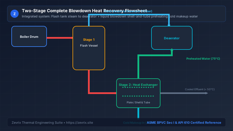
4. Two-Stage Heat Recovery Flowsheet Architecture
A modern, energy-efficient steam generation facility never discharges high-pressure blowdown directly to the sewer. Instead, a two-stage heat recovery system captures up to 85% of total sensible heat:
5. Cyclonic Flash Tank Steam Separation
In the first recovery stage, high-pressure blowdown enters a vertical cyclonic flash vessel operating at deaerator pressure (typically 1.2 to 2.0 bar abs):
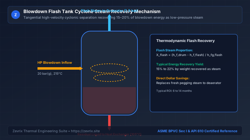
h_f,drum= Sensible heat enthalpy of saturated liquid at boiler drum pressure (kJ/kg)h_f,flash= Sensible heat enthalpy of saturated liquid at flash tank pressure (kJ/kg)h_fg,flash= Latent heat of vaporization at flash tank pressure (kJ/kg)
6. Worked Fuel Savings & ROI Case Study
Consider an industrial manufacturing plant operating a natural gas boiler with the following specifications:
- Steam Production: 40,000 kg/h (40 t/h) at 25 bar(g) (224°C, h_f = 962.0 kJ/kg)
- Feedwater TDS: 75 ppm | Max Drum TDS: 2,500 ppm
- Continuous Blowdown %: 3.09% →
Ṁ_blowdown = 1,236 kg/h - Flash Tank Operating Pressure: 1.5 bar(g) (127°C, h_f = 533.5 kJ/kg, h_fg = 2,181.5 kJ/kg)
- Cold Makeup Water Temp: 15°C (h_f = 63.0 kJ/kg)
- Natural Gas Cost: $9.50 per MMBtu ($0.0324 per kWh)
- Annual Operating Hours: 8,400 hours/year
Step 1: Calculate Stage 1 Flash Steam Recovery
Ṁ_flash_steam = 1,236 kg/h × 0.1964 = 242.8 kg/h clean steam to deaerator
Annual flash steam energy value: 242.8 kg/h × 2,717 kJ/kg × 8,400 h = 5.54 × 10⁹ kJ = 5,251 MMBtu/yr = $49,885/year.
Step 2: Calculate Stage 2 Residual Heat Exchanger Recovery
The remaining 993.2 kg/h of 127°C liquid passes through a counter-flow plate heat exchanger, cooling to 45°C before sewer discharge:
Annual heat exchanger energy value: 95.0 kW × 8,400 h × $0.0324/kWh = $25,855/year.
Total Combined Annual Savings: $49,885 + $25,855 = $75,740 per year.
With a turnkey equipment installation cost of $62,000 for the flash tank and plate heat exchanger package, the simple payback period is just 9.8 months.
Try the Zevrix Interactive Boiler Feed Pump Calculator
Enter your boiler evaporation rate, operating drum pressure, and feedwater temperature to calculate exact mass flow, TDH, motor ratings, and cavitation margins with complete formula visibility.
Frequently Asked Questions
Marcus Vance, PE, M.Sc.
AuthorSenior Thermal Hydraulics & Fluid Machinery Specialist
Marcus Vance is a registered Professional Engineer with over 18 years of field and design experience in thermal power generation, industrial boiler feedwater systems, and API 610 rotating machinery.