Boiler Feed Tank Sizing Principles: Deaerator Storage & Hydraulic Hold-Up Time
Determining net usable storage capacity, 10–20 minute MCR retention times, gross vessel geometry, and static head elevation to guarantee feed pump NPSHa.
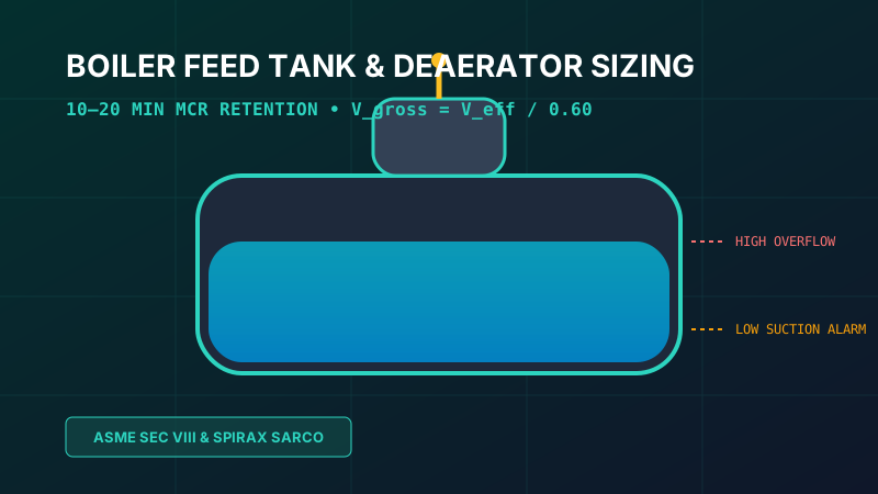
Table of Contents
The boiler feed tank—predominantly designed as a horizontal cylindrical deaerator storage vessel—serves as the primary thermal buffer and hydraulic reservoir in any industrial or utility steam generation loop. Sizing this vessel incorrectly creates catastrophic operational vulnerabilities: undersized vessels exhaust their water supply during minor makeup interruptions, forcing boiler emergency shutdowns, while oversized vessels represent massive structural deadweight requiring expensive elevated structural mezzanines.
1. Role of Deaerator Storage in the Steam Cycle
In modern thermal power plants and industrial facilities, the deaerator storage vessel performs four simultaneous functions:
- Hydraulic Reserve Buffer: Storing sufficient deaerated water to supply boiler Maximum Continuous Rating (MCR) steaming while raw water treatment or condensate return loops stabilize.
- Thermal Degasification Sinks: Maintaining water at saturation temperature (typically 105°C to 160°C) to reduce dissolved oxygen content below 7 ppb (0.007 mg/L) per Heat Exchange Institute (HEI) standards, preventing pitting corrosion in economizers and drum walls.
- Surge Capacity: Absorbing surging slugs of return condensate from batch industrial process consumers without lifting overflow relief valves.
- NPSH Head Source: Providing the primary static liquid head column (Z_static) required to satisfy boiler feed pump Net Positive Suction Head requirements (NPSHr).
2. Retention Time & MCR Sizing Criteria
The primary sizing metric for any boiler feed tank is retention time (also known as hold-up time or residence time) evaluated at the boiler's Maximum Continuous Rating (MCR) steam production rate.
| Facility Type & Operating Regime | Recommended Retention Time (Minutes @ MCR) | Design Justification |
|---|---|---|
| Packaged Firetube Boilers (Commercial) | 10 to 15 minutes | Small water inventory, fast thermal response, reliable city water makeup |
| Industrial Watertube Boilers (Refineries, Paper, Chemical) | 15 to 20 minutes | High condensate contamination risks, frequent batch process swings, critical uptime |
| Combined Cycle Power Plants (HRSG Baseload) | 12 to 15 minutes | Continuous steady-state operation, automated dual makeup redundancy |
| Coal / Biomass Utility Thermal Power | 15 to 25 minutes | Large drum volumes, lengthy trip recovery procedures, high thermal inertia |
3. Volume Partitioning & Level Settings
A fundamental error in vessel design is confusing gross vessel volume with net usable volume. A horizontal cylindrical deaerator vessel is partitioned into four distinct operating liquid zones.
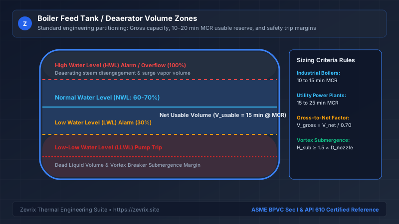
V_usable= Required net usable liquid storage volume (m³ or gallons)Ṁ_feed= Total boiler feedwater mass flow rate at MCR including blowdown (kg/h)t_retention= Selected retention time (minutes, typically 15 min)ρ(T_feed)= Saturated water density at deaerator operating temperature (kg/m³)
To ensure reliable operation without false trips, the gross vessel internal volume is calculated using an operational utilization factor:
K_utilization= Volumetric utilization factor (typically 0.65 to 0.70, reflecting that 30% to 35% of total volume is reserved for vapor disengagement and dead bottom submergence)
4. Cylindrical Geometry & Gross Sizing Formulation
Horizontal cylindrical pressure vessels with 2:1 semi-ellipsoidal or torispherical dished heads represent the standard industrial construction per ASME BPVC Section VIII Division 1. For structural stability and transportation limits, the length-to-diameter ratio (L/D) is typically constrained:
V_cylinder = ( π / 4 ) × D_internal² × L_shell
A vessel with L/D < 3 requires excessively thick head plates, while L/D > 5 creates severe longitudinal bending stresses requiring complex saddle supports and differential thermal expansion considerations.
5. Static Elevation & Pump NPSHa Coupling
The most critical interface between the boiler feed tank and the boiler feed pump is the static elevation difference. In a deaerator, the liquid in the vessel is in direct equilibrium with its vapor at saturation temperature.
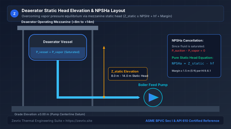
Because the water is boiling saturated liquid, P_vessel - P_vapor = 0. The fundamental equation for Net Positive Suction Head Available (NPSHa) simplifies directly to:
Z_static= Vertical distance from minimum liquid level (LLWL) in the tank to the pump centerline (m)h_f,suction= Friction head loss across downcomer pipe, isolation valve, strainer, and reducer (m)
To prevent cavitation damage per Hydraulic Institute (HI 9.6.1) standards, the deaerator vessel bottom elevation must satisfy:
6. Internal Mechanics: Trays vs Spray Scrubbers
Thermal deaeration relies on two mechanical designs to strip non-condensable corrosive gases:
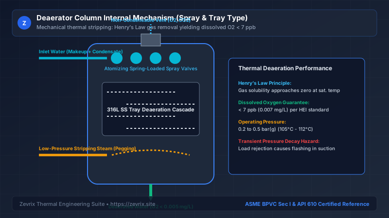
| Design Feature | Spray-Tray Deaerator (Two-Vessel) | Spray-Scrubber Deaerator (Single-Vessel) |
|---|---|---|
| Mechanical Turndown | 10:1 (Exceptional performance from 10% to 100% flow) | 4:1 (Performance degrades significantly below 25% flow) |
| Oxygen Removal Efficiency | Guaranteed < 5 ppb (0.005 mg/L) dissolved O2 | Typically 7 to 15 ppb dissolved O2 |
| Maintenance Requirements | Trays require periodic descaling in hard-water plants | Fewer internal parts; lower capital cost |
| Application Preference | Utility power plants, pulp & paper, heavy industry | Commercial heating, small industrial package boilers |
7. Step-by-Step Worked Sizing Example
Consider an industrial combined heat and power (CHP) plant with the following parameters:
- Boiler Steaming Rate: 80,000 kg/h (80 t/h) at MCR
- Continuous Blowdown: 2.5% → Feedwater demand = 82,000 kg/h
- Deaerator Temperature: 120°C (Pressurized at 1.98 bar abs)
- Water Density at 120°C: 943.1 kg/m³
- Required Retention Time: 15 minutes at full MCR
- Feed Pump NPSHr: 4.8 meters at rated flow
- Suction Piping Friction Loss: 0.40 meters
Step 1: Calculate Net Usable Volume
Step 2: Calculate Gross Tank Volume
Applying a standard 68% utilization factor (K_utilization = 0.68):
Step 3: Determine Cylindrical Shell Dimensions
Selecting a standard internal diameter D = 2.40 m (8 ft):
Shell Length L = 31.97 / 4.524 = 7.07 meters (23.2 ft)
L/D Ratio = 7.07 / 2.40 = 2.95 (Optimal structural proportion)
Step 4: Determine Minimum Mezzanine Elevation
The structural engineer specifies an operating mezzanine elevation of +7.50 meters above grade, ensuring an expansive 2.30 m safety buffer above NPSHr across all operating conditions.
Try the Zevrix Interactive Boiler Feed Pump Calculator
Enter your boiler evaporation rate, operating drum pressure, and feedwater temperature to calculate exact mass flow, TDH, motor ratings, and cavitation margins with complete formula visibility.
Frequently Asked Questions
Marcus Vance, PE, M.Sc.
AuthorSenior Thermal Hydraulics & Fluid Machinery Specialist
Marcus Vance is a registered Professional Engineer with over 18 years of field and design experience in thermal power generation, industrial boiler feedwater systems, and API 610 rotating machinery.