Pump Cavitation Diagnostics: NPSHa vs NPSHr & Transient Flashing Prevention
Fluid depression below vapor pressure, micro-jet bubble collapse mechanics, acoustic FFT vibration signatures, and anti-flashing suction piping design.
Table of Contents
Cavitation represents the single most destructive hydraulic failure mode encountered in high-energy boiler feed pump systems. In a matter of weeks, unmitigated cavitation can chew through solid cast chrome-steel impellers, shatter tungsten carbide mechanical seal faces, and destroy radial sleeve bearings through violent high-frequency pressure pulsations.
1. Fluid Dynamics & Micro-Jet Physics
Cavitation is often mischaracterized simply as "water boiling." In engineering thermodynamics, cavitation is a two-phase dynamic phenomenon that occurs strictly at constant temperature when localized static pressure drops below the fluid's saturation vapor pressure:
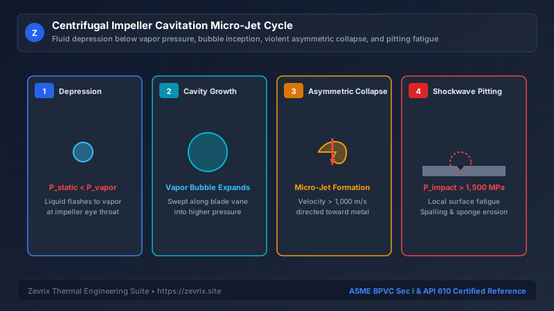
As water rounds the curvature of the impeller blade leading edge, fluid velocity spikes, causing static pressure to depress according to Bernoulli’s theorem. When P_static < P_vapor, microscopic gas nuclei expand into vapor cavities. As these bubbles are swept downstream into regions of higher pressure along the vane channel, the surrounding liquid crushes the bubble inward.
Because the bubble is positioned against a solid metallic surface, the surrounding pressure field is asymmetrical. The bubble collapses from the outer wall inward, forming a needle-thin liquid micro-jet that penetrates the bubble interior at velocities exceeding 1,000 m/s (3,300 ft/s). When this micro-jet strikes the metal, it produces localized shockwave pressures exceeding 1,500 MPa (217,000 psi)—well beyond the yield strength of commercial steels.
2. NPSHa Derivation in Saturated Liquid Systems
The fundamental metric governing cavitation margin is Net Positive Suction Head Available (NPSHa), defined as the total suction head above vapor pressure at the pump suction nozzle centerline:
In a boiler feedwater deaerator, the liquid in the vessel is saturated: the steam blanket pressure in the dome exactly equals the vapor pressure of the boiling liquid (P_suction = P_vapor). Under steady-state conditions, the pressure terms mathematically cancel out to zero:
This proves an indispensable engineering fact: Increasing deaerator dome pressure does NOT increase NPSHa! Elevating deaerator pressure simultaneously increases water temperature and vapor pressure by the exact same amount. The only way to increase NPSHa in a saturated system is to either increase static liquid elevation (Z_static) or reduce suction piping friction loss (h_f,suction).
3. Turbine Trip & Transient Pressure Decay Hazard
While steady-state NPSHa may appear generous on paper, feed pumps frequently cavitate violently during sudden plant electrical load rejections or steam turbine trips. This catastrophic phenomenon is known as Transient Deaerator Pressure Decay.
During a trip, the steam supply pegging the deaerator shuts off immediately. Condensing steam causes the deaerator vessel pressure to plunge within seconds. However, the water residing in the long downcomer pipe between the deaerator and the pump cannot cool instantly—it retains the higher temperature of the pre-trip state. When this hotter, high-vapor-pressure water reaches the pump inlet where vessel pressure has dropped, the water flashes into massive steam voids, causing total pump loss of prime.
4. FFT Spectral Analysis & Acoustic Diagnostics
Vibration monitoring is the primary predictive maintenance tool for detecting cavitation before mechanical failure occurs. Conventional overall velocity vibration (0 to 1,000 Hz) rarely detects early cavitation. True diagnostic detection requires Fast Fourier Transform (FFT) spectrum analysis combined with high-frequency acoustic demodulation (PeakVue, Shock Pulse, or Ultrasonic Envelope).
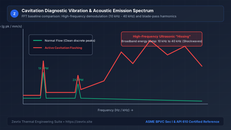
| Diagnostic Frequency Band | Physical Origin | Normal Condition | Cavitating Condition |
|---|---|---|---|
| 1X RPM (e.g. 50 Hz / 60 Hz) | Mechanical unbalance, shaft centerline | < 1.5 mm/s RMS | Stable or slightly elevated by asymmetric voids |
| Blade Pass Frequency (BPF = Vanes × RPM) | Impeller blade vane passing diffuser vanes | Low discrete spike | Fluctuating sidebands caused by vapor cavity pulsation |
| High-Frequency Broadband (10 kHz to 40 kHz) | Shockwave micro-jet implosions against metal | Flat, near-zero acoustic noise floor | Massive elevated "hump" (300% to 800% above baseline) |
5. Anti-Flashing Suction Piping Architecture
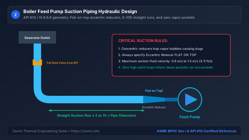
Over 70% of chronic feed pump cavitation issues stem from poor suction piping geometry. Complying with Hydraulic Institute (HI 9.6.6) and API 610 design standards eliminates fluid pre-rotation, velocity distortion, and trapped vapor pockets:
| Piping Component | Engineering Specification | Fluid Mechanical Rationale |
|---|---|---|
| Suction Fluid Velocity | 0.9 m/s to 1.5 m/s (3 to 5 ft/s) | Minimizes friction head loss; prevents turbulence |
| Straight Pipe Run | ≥ 5 to 10 × Pipe Diameters | Stabilizes velocity profile into impeller eye |
| Pipe Reducer | Eccentric REDUCER (Flat on top strictly) | Eliminates high-point pocket where steam accumulates |
| Suction Isolation Valve | Full-port Gate or Butterfly with horizontal stem | Eliminates localized throttling and eddy shedding |
6. Impeller Metallurgy & Cavitation Resistance
When operating near thermodynamic saturation, selecting cavitation-resistant alloys prevents metal erosion:
| Impeller Material & Grade | Relative Cavitation Resistance | Typical Service Life in Cavitating Feedwater |
|---|---|---|
| Cast Iron (ASTM A48 Class 30) | 1.0 (Baseline reference) | Unsuitable; rapid erosion within 500 hours |
| Carbon Steel (ASTM A216 WCB) | 2.5 × baseline | Poor; susceptible to flow-accelerated corrosion (FAC) |
| 12% Chrome Steel (ASTM A743 CA6NM) | 15.0 × baseline | Standard industry choice for API 610 boiler feed pumps |
| Duplex Stainless (ASTM A890 Grade 4A) | 25.0 × baseline | High yield strength; superior resistance to micro-jet pitting |
7. Field Troubleshooting Matrix
| Observed Field Symptom | Likely Root Cause | Diagnostic Verification Method | Immediate Corrective Action |
|---|---|---|---|
| "Gravel" rattling noise at 100% load | Insufficient steady-state NPSHa | Inspect suction pressure transmitter; check strainer drop | Clean clogged suction strainer; elevate deaerator level |
| Vibration spikes immediately following boiler load drop | Deaerator transient pressure decay flashing | Compare rate of pressure decay (dP/dt) to suction temperature | Install cold-water injection quench or deaerator pegging steam boost |
| Loud rumbling at low flow (< 25% BEP) | Suction and discharge recirculation (NOT low NPSH) | Noise intensifies as flow decreases; vanishes at 100% flow | Open minimum continuous stable flow (MCSF) bypass valve |
| Intermittent surges with rattling | Concentric reducer trapping steam slug | Visual inspection of piping isometric drawing | Re-pipe suction with eccentric reducer flat on top |
Try the Zevrix Interactive Boiler Feed Pump Calculator
Enter your boiler evaporation rate, operating drum pressure, and feedwater temperature to calculate exact mass flow, TDH, motor ratings, and cavitation margins with complete formula visibility.
Frequently Asked Questions
Marcus Vance, PE, M.Sc.
AuthorSenior Thermal Hydraulics & Fluid Machinery Specialist
Marcus Vance is a registered Professional Engineer with over 18 years of field and design experience in thermal power generation, industrial boiler feedwater systems, and API 610 rotating machinery.