Boiler Feed Pump Calculation: The Comprehensive Hydraulic Sizing Handbook
Step-by-step mathematical derivations for feedwater mass flow, IAPWS-IF97 fluid density conversion, Total Dynamic Head (TDH), and electric motor sizing per ASME BPVC Sec I & API 610.
Table of Contents
The boiler feed pump (BFP) represents the mechanical heart of any steam-generating industrial facility, district heating network, or thermal utility power station. Operating under extreme thermodynamic conditions, feed pumps are tasked with injecting subcooled or saturated water into boiler steam drums operating at pressures ranging from 10 bar(g) in small industrial package units up to 180+ bar(g) in supercritical utility boilers.
An undersized feed pump leads directly to boiler water starvation, emergency low-level tripouts, and catastrophic thermal stress on boiler tubes. Conversely, an oversized pump incurs massive electrical throttling losses, operates chronically below its Best Efficiency Point (BEP), and suffers premature mechanical seal and bearing failures caused by internal hydraulic recirculation.
1. Introduction & Operational Stakes
In modern steam plant architecture, the feed pump does not operate in isolation. It forms the critical hydraulic bridge between the low-pressure deaerator storage tank (typically 0.2 to 0.5 bar(g) at 105°C to 112°C) and the high-pressure boiler drum. Designing this system requires simultaneous mastery of four disciplines:
- Thermodynamic mass and energy conservation: Accounting for steam generation, continuous surface blowdown, sootblowing, and desuperheater attemperation spray water.
- Equation of State fluid mechanics: Utilizing the IAPWS-IF97 formulation to capture non-linear density and vapor pressure variations across wide temperature regimes.
- Total Dynamic Head (TDH) analysis: Factoring in boiler drum operating pressure, safety valve accumulation settings, piping friction, control valve authority, and economizer drop.
- Rotating machinery selection: Complying with API 610 / ISO 13709 standards for casing configuration, rotor dynamics, radial thrust balance, and driver sizing margins.
2. Feedwater Mass Flow Balance Derivation
The sizing process begins with fundamental mass conservation. A common operational error is sizing the feed pump solely to match the boiler's rated steam output. In reality, modern steam boilers must purge a continuous liquid stream—termed continuous surface blowdown—to control Total Dissolved Solids (TDS), silica, and electrical conductivity within limits prescribed by ASME and the American Boiler Manufacturers Association (ABMA).
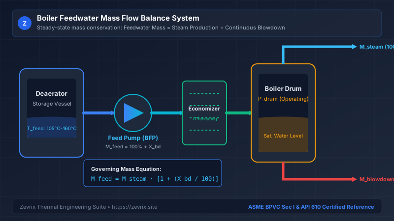
The steady-state mass balance across the boiler drum boundary is defined by:
Ṁ_feed= Total required feedwater mass flow rate (kg/h or lb/h)Ṁ_steam= Boiler Maximum Continuous Rating (MCR) steam production (kg/h or lb/h)X_blowdown= Continuous surface blowdown rate expressed as a percentage of steam flow (%)Ṁ_attemp= Superheater attemperator desuperheating spray water demand (kg/h, if tapped upstream of economizer)
Once the operating mass flow rate is established, an engineering safety margin is applied per industry guidelines (such as ASME Section I or API 610) to account for rapid drum level recovery following sootblowing, plant load transients, and pump internal wear over time:
Q_design= Pump rated volumetric flow rate (m³/h or gpm)ρ(T_feed)= Feedwater density at deaerator operating temperature (kg/m³ or lb/ft³)S_flow= Design flow service factor (typically 1.10 to 1.15, representing a 10% to 15% safety margin)
3. Fluid Thermodynamics & IAPWS-IF97 Density
Water is frequently assumed to have an incompressible density of 1,000 kg/m³ (8.34 lb/gal). In boiler engineering, adopting this ambient simplification introduces severe sizing errors. Feedwater entering the pump suction originates from a thermal deaerator operating between 105°C (221°F) and 160°C (320°F). At these elevated temperatures, thermal expansion significantly reduces liquid density.
| Feedwater Temp (°C) | Saturation Press (bar abs) | Density ρ (kg/m³) | Specific Volume (m³/kg) | Volumetric Flow Multiplier |
|---|---|---|---|---|
| 20°C (Ambient ref) | 0.023 bar | 998.2 kg/m³ | 0.001002 | 1.000 (Base) |
| 105°C (Atm. Deaerator) | 1.208 bar | 954.7 kg/m³ | 0.001047 | 1.046 (+4.6%) |
| 120°C (Pressurized DA) | 1.985 bar | 943.1 kg/m³ | 0.001060 | 1.058 (+5.8%) |
| 140°C (Co-gen DA) | 3.614 bar | 926.1 kg/m³ | 0.001080 | 1.078 (+7.8%) |
| 160°C (High-pressure DA) | 6.181 bar | 907.3 kg/m³ | 0.001102 | 1.100 (+10.0%) |
As shown in the table above, feedwater at 160°C requires 10.0% greater volumetric capacity for the exact same mass flow rate than ambient water. Sizing a pump using ambient density will result in a pump that is physically incapable of delivering the required mass of water to the steam drum.
4. Total Dynamic Head (TDH) Mathematical Formulation
Centrifugal pumps do not generate pressure; they generate head, which is energy per unit weight of fluid (expressed in meters or feet of liquid column). The Total Dynamic Head (TDH) is the algebraic difference between the total discharge head and the total suction head referenced to the pump centerline:
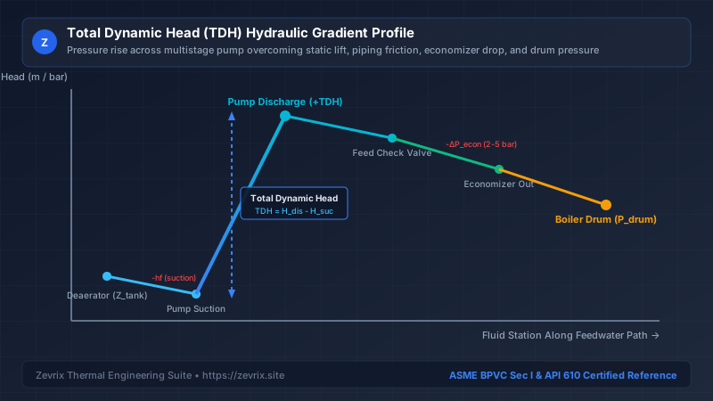
To derive H_discharge, the engineer must sum five distinct hydraulic components:
P_drum= Normal boiler drum operating gauge pressure (Pa)1.05= ASME Section I accumulation factor (5% margin above drum operating setpoint)ΔP_piping= Dynamic friction loss in discharge piping at design flow (Pa)ΔP_valves= Pressure drops across discharge check valves, isolation valves, and strainers (Pa)ΔP_econ= High-velocity pressure drop across the economizer tube bundle (typically 2 to 5 bar)ΔP_feedreg= Pressure drop across the modulating feedwater regulating valve (minimum 1.5 to 3.0 bar to ensure control authority)Z_drum= Static elevation difference between pump centerline and boiler drum water level (m)g= Acceleration due to gravity (9.80665 m/s²)
Similarly, the total suction head is determined by the deaerator vessel conditions:
P_deaerator= Deaerator operating pressure (Pa)Z_tank= Static liquid elevation of deaerator normal liquid level above pump centerline (m)h_f,suction= Suction piping friction head loss including strainer, fittings, and suction isolation valve (m)
5. Hydraulic Power, BHP & Motor Rating Calculation
With design volumetric flow rate (Q_design) and Total Dynamic Head (TDH) established, the energy imparted to the fluid is calculated as hydraulic power:
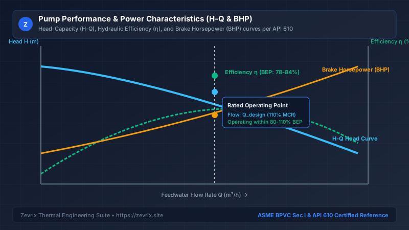
Due to mechanical friction in bearings and mechanical seals, disc friction on impeller shrouds, and hydraulic losses (recirculation, skin friction, and shock losses), the pump consumes Brake Horsepower (BHP) from the driver:
η_pump= Multistage centrifugal pump efficiency at the rated design point (typically 0.72 to 0.82 for high-pressure multistage units)
Per API 610 Section 6.1.4 and Table 14, electric motor drivers must feature a nameplate rating exceeding the maximum expected operating shaft power according to the following criteria:
| Motor Power Rating Range | API 610 Minimum Driver Margin | Standard IEC / NEMA Frame Selection Rule |
|---|---|---|
| < 22 kW (< 30 HP) | 125% of maximum rated pump BHP | Next standard commercial kW / HP rating above 1.25 × BHP |
| 22 kW to 75 kW (30 to 100 HP) | 115% of maximum rated pump BHP | Next standard commercial kW / HP rating above 1.15 × BHP |
| > 75 kW (> 100 HP) | 110% of maximum rated pump BHP | Next standard commercial kW / HP rating above 1.10 × BHP |
6. Comprehensive Worked Industrial Case Study
To demonstrate the practical application of this methodology, consider an industrial chemical plant operating a natural-circulation water-tube steam boiler with the following design specifications:
- Steam Production (MCR): 50,000 kg/h (50.0 t/h)
- Continuous Blowdown Rate: 3.0% of steam generation
- Boiler Operating Drum Pressure: 42.0 bar(g) (4,200 kPa)
- Deaerator Pressure: 0.5 bar(g) (150 kPa abs)
- Feedwater Temperature: 111.4°C (Saturated liquid in DA)
- Static Head Elevation (Z_drum - Z_tank): 14.0 meters
- Economizer Pressure Drop: 3.2 bar
- Discharge Piping & Valve Friction: 2.8 bar
- Feedwater Control Valve Drop: 2.5 bar
- Suction Piping Friction Loss: 0.45 meters head
- Estimated Multistage Pump Efficiency: 76.0% (0.76)
Step 1: Calculate Feedwater Mass Flow Rate
Step 2: Determine Fluid Density from IAPWS-IF97
At 111.4°C, water density is ρ = 950.2 kg/m³. Applying a 10% design flow safety factor (S_flow = 1.10):
Q_design = 54.20 × 1.10 = 59.62 m³/h (262.5 US gpm)
Step 3: Calculate Discharge Pressure & Head
Applying the ASME Section I 5% accumulation margin to drum pressure:
P_discharge = 44.10 + 3.2 (econ) + 2.8 (piping) + 2.5 (reg valve) = 52.60 bar(g) = 5,260 kPa
H_discharge = ( 5,260,000 / [ 950.2 × 9.80665 ] ) + 14.0 = 564.48 + 14.0 = 578.48 m
Step 4: Calculate Suction Head & TDH
TDH = H_discharge - H_suction = 578.48 - 10.92 = 567.56 meters (1,862 ft)
Step 5: Power and Motor Sizing
P_brake = 87.58 / 0.76 = 115.24 kW (154.5 BHP)
Since P_brake > 75 kW, API 610 requires a minimum 10% motor margin:
P_motor,min = 115.24 × 1.10 = 126.76 kW.
The engineer selects the next standard IEC electric motor frame rating: 132 kW (177 HP), 2-pole (2,980 RPM).
7. Common Engineering Pitfalls & Diagnostics
| Design Error / Field Symptom | Physical Root Cause | Operational Consequence | Corrective Engineering Action |
|---|---|---|---|
| Neglecting Economizer Pressure Drop | Failing to account for tube fouling and thermal boundary layer drop | Pump cannot feed water when boiler approaches 100% MCR | Measure baseline clean drop and add 35% fouling factor to discharge head calculation |
| Using Ambient 20°C Water Density | Assuming ρ = 1,000 kg/m³ instead of 900–950 kg/m³ | Under-sizing volumetric flow by 5% to 10% | Always apply IAPWS-IF97 steam table properties at deaerator operating temperature |
| Oversizing Pump by > 35% | Stacking excessive arbitrary "safety margins" | Pump runs far to the left of BEP, causing severe internal recirculation | Limit cumulative flow margin to 10–15% and verify MCSF recirc valve capacity |
| Ignoring Safety Valve Popping Pressure | Sizing discharge head to normal drum pressure instead of MAWP + 5% | Safety valves open during trip, drum pressure spikes, pump dead-heads | Incorporate full ASME Section I accumulation criteria into TDH calculation |
Try the Zevrix Interactive Boiler Feed Pump Calculator
Enter your boiler evaporation rate, operating drum pressure, and feedwater temperature to calculate exact mass flow, TDH, motor ratings, and cavitation margins with complete formula visibility.
Frequently Asked Questions
Marcus Vance, PE, M.Sc.
AuthorSenior Thermal Hydraulics & Fluid Machinery Specialist
Marcus Vance is a registered Professional Engineer with over 18 years of field and design experience in thermal power generation, industrial boiler feedwater systems, and API 610 rotating machinery.