Boiler Economizer Pressure Drop: Hydraulic Resistance, Steaming Hazards & Pump Head Margin
Darcy-Weisbach formulations, Colebrook-White friction factors, velocity optimization, internal magnetite fouling penalties, and steaming economizer prevention.
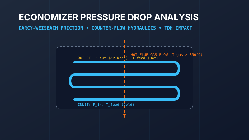
Table of Contents
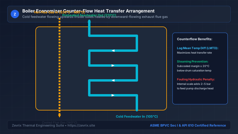
The boiler economizer is a crucial heat recovery heat exchanger that captures waste sensible heat from flue gases exiting the furnace to preheat incoming feedwater before it enters the steam drum. For every 6°C (11°F) increase in feedwater temperature achieved in the economizer, boiler overall thermal efficiency improves by approximately 1%, resulting in massive fuel savings.
1. Thermodynamic Function & Hydraulic Architecture
2. Darcy-Weisbach Pressure Drop Derivation
Total hydraulic pressure drop across the economizer consists of tube friction, 180° return bends, and inlet/outlet header expansion losses:
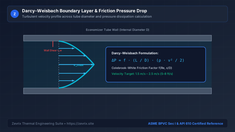
f= Darcy-Weisbach friction factor calculated via the Colebrook-White equationL_total= Total equivalent developed length of all tube circuits (m)D_internal= Internal tube diameter (m)ρ= Average fluid density evaluated at mean economizer temperature (kg/m³)v= Mean feedwater flow velocity inside tubes (m/s)
The Colebrook-White equation for turbulent flow in commercial steel tubes (Re > 4,000) is formulated as:
ε= Absolute tube roughness (typically 0.045 mm for drawn steel tubes)Re= Reynolds number:Re = ( ρ × v × D_internal ) / μ
3. The Steaming Economizer Hazard & Subcooling Margin
An economizer must be designed as a non-steaming heat exchanger under normal operating regimes:
If boiler firing rate increases while feedwater flow drops, the water temperature in the top tubes reaches saturation temperature (T_econ,out = T_drum,sat). Water flashes into steam inside the tubes. Because steam has a specific volume over 20 times greater than water at 40 bar, this phase change triggers severe choked flow, violent slug-flow water hammer that ruptures return u-bends, and emergency boiler low-level trips.
4. Optimal Feedwater Tube Velocity Limits
| Design Velocity Range | Hydraulic Consequence | Thermal Consequence | Engineering Assessment |
|---|---|---|---|
| < 0.9 m/s (< 3.0 ft/s) | Very low pressure drop (< 0.5 bar) | Poor heat transfer coefficient; risk of localized steaming | Unacceptable; requires excessive tube surface area |
| 1.2 m/s to 2.2 m/s (4 to 7 ft/s) | Moderate pressure drop (1.5 to 3.0 bar) | High Reynolds number (turbulent); excellent heat transfer | Zevrix Optimal Target: Ideal balance of pump power & efficiency |
| > 3.0 m/s (> 10.0 ft/s) | Excessive pressure drop (> 6.0 bar) | Negligible heat transfer gain; erosion-corrosion at bends | Unacceptable; severely inflates feed pump driver kW |
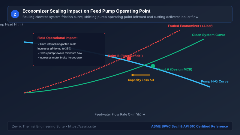
5. Magnetite Scaling & Pump Head Degradation
6. Complete Worked Engineering Calculation
Consider an industrial watertube boiler generating 60,000 kg/h of steam at 45 bar(g) (T_drum,sat = 258.8°C):
- Feedwater Flow Rate: 61,800 kg/h (including 3% blowdown) = 17.17 kg/s
- Economizer Inlet Temp: 115°C (
ρ_in = 947 kg/m³) - Economizer Outlet Temp: 225°C (
ρ_out = 834 kg/m³, Subcooling margin =258.8 - 225 = 33.8°C) - Average Fluid Density:
ρ_avg = 890.5 kg/m³ - Tube Bank Dimensions: 24 parallel tube circuits, 38 mm OD × 3.6 mm wall thickness (
D_internal = 30.8 mm = 0.0308 m) - Equivalent Tube Length per Circuit: 85 meters (including 14 return bends)
Step 1: Calculate Water Velocity in Tubes
Tube Cross-Sectional Area A = ( π / 4 ) × (0.0308)² = 0.000745 m²
Tube Velocity v = 0.7154 / ( 890.5 × 0.000745 ) = 1.078 m/s (Within optimal 1.0–2.0 m/s range)
Step 2: Determine Friction Factor via Colebrook
Reynolds Number Re = ( 1.078 × 0.0308 ) / ( 0.185 × 10⁻⁶ ) = 179,500 (Fully turbulent)
Relative Roughness ε / D = 0.045 / 30.8 = 0.00146 → Darcy Friction Factor f = 0.0224
Step 3: Calculate Pressure Drop
Bends & Header Losses (14 bends × K=0.4 + headers) = 1.85 bar
Total Clean Economizer ΔP = 2.17 bar (31.5 psi)
Step 4: Sizing Head Allowance for 35% Fouling
To ensure the boiler feed pump can supply full MCR flow after 2 years of continuous operation with internal scale:
Head Penalty = ( 293,000 Pa ) / ( 890.5 kg/m³ × 9.80665 m/s² ) = 33.5 meters of head
The pump hydraulic specification must explicitly budget 33.5 meters (110 ft) of Total Dynamic Head solely to overcome the fouled economizer assembly.
Try the Zevrix Interactive Boiler Feed Pump Calculator
Enter your boiler evaporation rate, operating drum pressure, and feedwater temperature to calculate exact mass flow, TDH, motor ratings, and cavitation margins with complete formula visibility.
Frequently Asked Questions
Marcus Vance, PE, M.Sc.
AuthorSenior Thermal Hydraulics & Fluid Machinery Specialist
Marcus Vance is a registered Professional Engineer with over 18 years of field and design experience in thermal power generation, industrial boiler feedwater systems, and API 610 rotating machinery.